12 Managing UI Geometry
One of the more difficult aspects of programming a graphically oriented application is positioning the user interface components on the screen. Developers often have to manually place buttons, size dialog boxes, and draw frames and titles. The GEOS Geometry Manager lets you ignore most of these issues.
The geometry manager allows you to ignore position, size, and spacing of your generic UI components; if you use visual objects, the geometry manager can calculate object sizes and positions, dynamically changing them as necessary. Because the geometry manager works at run-time, you have to do very little in the way of screen management. Instead, you can set various attributes and hints to fine-tune your UI’s appearance.
Before reading this chapter, you should be familiar with the GEOS User Interface in general and the generic UI in specific. For most of this chapter, “First Steps: Hello World,” Chapter 4, will be sufficient background information; for other sections, you should at least read “The GEOS User Interface,” Chapter 10.
12.1 Geometry Manager Overview
The GEOS geometry manager is an algorithmic mechanism which interacts directly with the UI to position and size objects of all types. The geometry manager automatically manages all generic objects through interactions with the specific UI library; you can also use it to manage your visible object trees.
The Geometry Manager is what makes the generic UI possible: Since geometry of UI objects (size and position) is determined by the UI at run-time, generic UI objects do not have to be explicitly defined with certain geometry. With this feature, a specific UI library can set up the UI geometry as it wants.
Your first interaction with the geometry manager will be when you build a generic object tree for your UI. Most hints applied to an object are signals to the geometry manager about how the object should be positioned, sized, or otherwise placed on the screen. These hints are all defined in GenClass, the topmost generic object class, so they are available (though not necessarily useful) to all types of generic objects.
This chapter first describes the features of the geometry manager and how the mechanism fits into the GEOS system as a whole (later in this section). Then it discusses how to manage generic UI objects (using a dialog box as an example) in section 12.2. For the hints you can apply to window objects, see section 12.3. For descriptions of managing the geometry of visible object trees and composites, see “VisClass,” Chapter 23 of the Object Reference Book.
12.1.1 Geometry Manager Features
The geometry manager, used effectively, can take nearly all the work out of displaying, sizing, and positioning objects on the screen. Many of the tasks you normally would have to do to create even a simple dialog box are taken care of automatically by the geometry manager and the specific UI library. Among the functions the geometry manager performs are the following:
Window Positioning and Sizing
The geometry manager interacts directly with the UI to determine where windows should be placed and what their dimensions should be. You have some control over this with hints, messages, and object instance data, and often you will have to choose a hint to determine the window position or size.Object Sizing
The size of an object can be determined by the combined sizes of its children, by the limits of its parent, or specifically by other constraints on the object. The geometry manager allows all three types of sizing behavior. The first two are implemented automatically in geometry updates; the third depends on how the application wants to manage the “other constraints.”Object Positioning
The position of an object can be determined either by the object or by the geometry manager. The geometry manager can position objects based on several criteria including the spacing of siblings in a composite, the size and/or location of the parent composite, and the justification hints applied to the object. Visible objects can control very closely how and where they are positioned; generic objects can determine how positioning occurs with various hints.Automatic Geometry Updating
Typically, when a particular object in a tree is resized, repositioned, added, or removed, the object mechanisms will mark the geometry of both that object and its parent invalid. This will invoke the geometry manager, which will traverse the object tree, determine which objects are affected by the potential geometry change, and then update the size and position of all affected objects up to the top of the tree. This entire process is automatic for generic objects; for visual objects, you may or may not have to mark the object invalid yourself, depending on the depth of custom geometry control you use.
With geometry functions covered by the geometry manager and drawing functions covered by the specific UI library, you have little else to do but specify the structure of your object tree and the hints each object should have. The system does all the dirty work of drawing and managing the objects on the screen, leaving you free to work on your application rather than on its graphical screen representation.
12.1.2 How Geometry Is Managed
The geometry manager is one part of the system that draws objects on the screen and redraws them when necessary. This system is called the “visual update mechanism.”
The visual update mechanism is invoked any time the geometry or image of an object is marked invalid. If only the image is invalid, typically no geometry calculations will be done. If, however, the geometry of an object is marked invalid, the geometry manager is called in to calculate the new size and position of all the affected objects in the object tree.
Normally, you won’t have to do any more than set certain hints (for generic objects) or attribute flags (for visible objects) to get the desired geometry behavior. If, however, you plan on modifying how the geometry of a particular set of objects is set, you will want to understand the sequence of events that happen during a geometry update. Typically, only programmers who are building their own specific UI libraries and those who have complex visual object trees will need to understand the geometry calculation sequence.
The geometry manager’s calculation can be thought of as a multiple-pass, recursive algorithm. It traverses the object tree, managing geometry within each composite until it reaches the top-most object that is unaffected by the geometry calculations.
The geometry update process is invoked when an object has its geometry marked invalid. This is determined by the object’s visual flags (its VI_optFlags field), VOF_GEOMETRY_INVALID and VOF_WINDOW_INVALID. If either of these flags is set, the object’s geometry requires recalculation.
The geometry manager sends MSG_VIS_UPDATE_GEOMETRY to the visible object with invalid geometry. This message determines which objects in the tree are potentially affected by the geometry update, and then it recalculates the tree’s geometry.
If the object initially marked invalid is a composite, all its children are automatically included in the update. If the object is a child of a composite, the geometry manager will travel up the tree, marking any parents and siblings that also require recalculation. (Recalculation does not cross VTF_IS_WIN_GROUP boundaries, however. A VTF_IS_WIN_GROUP is any windowed object; geometry calculations generally do not cross windowed objects (move into another window layer) unless explicitly instructed to do so.)
The geometry manager then returns to the bottom-most affected object in the tree and sends it a MSG_VIS_RECALC_SIZE. This message passes the object a suggested size, which will be the same as the object’s original size. (The original size is passed as an optimization in case the object does not need its geometry changed; many changes will affect many objects but will actually change only a few.)
The object then returns its new desired size based on the geometry change. If this is the original object marked invalid, the returned size will be the direct result of the geometry change. If this object is a descendent of the invalid object, it may not want to change its geometry at all and may therefore return its current size.
The geometry manager collects the returned sizes of all siblings at a given level and calculates the suggested size of their parent composite. The parent composite is then sent MSG_VIS_RECALC_SIZE with the newly calculated size and returns the size it wants to be as a result. (Some composites will have fixed, maximum, or minimum sizes or may have their sizing tied to other factors; these objects may return a different size.) If the returned size is different from the passed size, the geometry manager arbitrates between the objects. Typically, the composite will be grown large enough (even if fixed or maximum size) to fit all its children.
The geometry manager will go up the tree in this manner, calculating the new geometry of each child and then each composite until it reaches an object that is unaffected by the geometry change. (For example, if a child shrinks but other children cause the composite to remain the same size, the geometry update will stop at the composite because objects higher up are not affected.) If all objects in the tree are affected by the change, the geometry update will stop at the topmost object in the branch (the first VTF_IS_WIN_GROUP object).
If any parent objects disagree with their children on the new size, the geometry manager will arbitrate. The geometry manager may make several passes to suggest width and height changes to both the child and parent before deciding on an ultimate geometry. The geometry manager may alter child spacing, wrap the children, grow the composite, or even clip the children if necessary. A result will quickly be reached, however-the geometry manager will not thrash between the parent and children (unless you subclass MSG_VIS_RECALC_SIZE or MSG_VIS_GET_CENTER and do not pay close attention to how the message is handled).
After the geometry is recalculated up to the first VTF_IS_WIN_GROUP object (or up to the top affected object), a MSG_VIS_NOTIFY_GEOMETRY_VALID will be sent to each of the invalid objects that have VGA_NOTIFY_GEOMETRY_VALID set in their VI_attrs field. A visual update will then be started to draw the new geometry to the screen. Once a branch’s geometry has been calculated, the branch will remain unaffected until the next time the geometry of one of its objects is marked invalid.
If a recalculation of a branch’s geometry causes a VTF_IS_WIN_GROUP object to change its size or position, the window system will determine the effects. For example, if a VisContent object grows as a result of a geometry change, it will send a MSG_GEN_VIEW_SET_DOC_BOUNDS to the GenView; the geometry recalculation mechanism will not scroll the content-view connection. What happens to the view and its parent window then depends on the attributes of the view. For example, if the view is set to follow the size of its content, it will grow, bumping the size of its parent in the process. If the view is scrollable, it likely will stay the same size.
12.2 Arranging Your Generic Objects
The process of arranging user interface elements for a GEOS application differs drastically from that of traditional user interface programming methods. In most graphical systems, you must manually determine the location of each and every user interface element. For instance, to design a dialog box, you have to figure the location of each text string, button, and list entry. Normally, these items would have to be hard-coded into your application, and often different video resolutions would have to be taken into account.
Not so in GEOS. The generic and specific UI libraries work with the geometry manager to automatically arrange your generic UI objects in the most appropriate way. To describe a dialog box in GEOS, for instance, you simply have to define the objects contained in the dialog box and their relative positions in the generic object tree; GEOS does the rest, determining the position and visual effects of each object. You can even fine-tune the appearance of each object with the use of hints.
12.2.1 General Geometry Rules
You may feel at first that the use of generic UI components limits your control over the UI of your application. Actually, just the opposite is true: Your application becomes immediately available at all supported video resolutions in all available specific UIs. Additionally, you can concentrate on more important issues of your application; the generic UI objects take care of a tremendous amount of the work in positioning and displaying the user interface.
To determine your generic UI tree, you must remember that UI geometry is determined by three things: First and foremost, the overall structure of the UI is governed by the structure and organization of the generic object tree. For example, if GenTriggers A, B, and C are designated as children of a dialog box, they will likely be ordered in the same order they’re listed in the dialog’s GI_comp field.
Second, an object’s attributes can determine its implementation. For example, the GIGI_visibility field of a GenInteraction can determine whether the interaction is implemented as a dialog box, a menu, or a grouping object. The attributes of a generic object determine the basic functionality of the object; that is, even though a menu might be implemented differently in different specific UIs, the functionality of a menu will be implemented in the object. The manner of display of an object is based on its functionality. In this way, the attributes of a generic object take precedence over hints.
Third, an object’s behavior can be fine-tuned through the use of hints. Hints may or may not be implemented for each object that has them, and they control less strictly how the object works.
12.2.1.1 Generic Tree Structure
As stated above, the structure of your application’s generic object tree determines how the generic UI objects will be organized. A simple example of a generic tree including a menu, a dialog box, and a GenView can be found in “First Steps: Hello World,” Chapter 4.
12.2.1.2 How Hints Work
Nearly all geometry of generic UI objects is determined by hints. You can position, size, and limit generic objects with different hints. All these hints are defined in GenClass; inheritance allows all generic objects to have them, though not all hints are applicable to all generic objects.
Hints are described in detail in “GenClass,” Chapter 2 of the Object Reference Book, but the basics are reviewed here for convenience. Hints are implemented as variable data entries; each hint is a different variable-data type. Hints therefore take up instance data space in an object only when the object has that hint.
As stated earlier, not all hints are appropriate for all objects. For example, HINT_CUSTOM_CHILD_SPACING is probably not useful when applied to a GenTrigger object because a GenTrigger can have no children. Hints, by definition, are also not guaranteed to be supported by all specific UI libraries. For example, a specific UI might require all elements of a dialog box to be oriented horizontally; in this case, HINT_ORIENT_CHILDREN_VERTICALLY might be useful but might not be heeded by the specific UI.
Because geometry management of generic objects can be confusing at times, this chapter follows a series of examples accompanied with diagrams. For the most part, you should be able to “plug and play” the examples in the following sections.
12.2.2 Orienting Children
HINT_ORIENT_CHILDREN_HORIZONTALLY, HINT_ORIENT_CHILDREN_VERTICALLY, HINT_ORIENT_CHILDREN_ALONG_LARGER_DIMENSION, HINT_SAME_ORIENTATION_AS_PARENT
The two hints HINT_ORIENT_CHILDREN_HORIZONTALLY and HINT_ORIENT_CHILDREN_VERTICALLY, when used in a composite object, determine the orientation of the composite’s children. A composite object can orient its children either horizontally or vertically. The geometry manager will determine the combined size of the children and any margins or spacing set up (none by default) and will size the composite to the minimum required by its children.
Children oriented horizontally will typically be top-justified, and children oriented vertically will be left-justified. (This is default behavior changeable either with the use of hints or by the specific UI.) The vertical composite will size to the width of the widest child; the horizontal composite will size to the height of the tallest child.
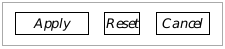
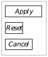
Figure 12-1 Horizontal and Vertical Composites
The bounds of the composites are designated by the dashed boxes. The Goc code for these composites is shown in the following display.
Code Display 12-1 Orienting a Composite
        /* Composite oriented horizontally */
@object GenInteractionClass MyInteraction = {
    GI_comp = @ApplyTrigger, @ResetTrigger, @CancelTrigger;
    HINT_ORIENT_CHILDREN_HORIZONTALLY;
}

        /* Composite oriented vertically */
@object GenInteractionClass MyOtherInteraction = {
    GI_comp = @ApplyTrigger, @ResetTrigger, @CancelTrigger;
    HINT_ORIENT_CHILDREN_VERTICALLY;
}
A large example of a complex dialog box is shown in Figure 12-2. This dialog box uses nested GenInteraction objects to achieve a complex grouping of children. Using the many justification, spacing, and orientation hints described throughout the chapter, you can change and fine-tune the appearance of the dialog box. The code that implements this dialog box is shown in Code Display 12-2.
Two other hints may be useful for arranging children, especially in toolboxes. These two hints are not shown in the examples, though they are used prominently with tool groups.
HINT_SAME_ORIENTATION_AS_PARENT is used by one windowed object (GenInteraction) when it should orient its children in the same way its parent does. This, too, is useful for toolboxes because you can set an orientation in the toolbox, then set HINT_SAME_ORIENTATION_AS_PARENT in the tool group.

Figure 12-2 A Complex Dialog Box
GenInteraction objects may be nested, and they may be oriented just as other children. The code for this example is shown in the following display.
HINT_ORIENT_CHILDREN_ALONG_LARGER_DIMENSION allows you to orient a composite’s children along the screen’s larger dimension. The hint will work like HINT_ORIENT_CHILDREN_HORIZONTALLY if the screen is wider than it is tall; it will work like HINT_ORIENT_CHILDREN_VERTICALLY if the screen is taller than it is wide.
Code Display 12-2 A Complex Dialog Box
/* This code display shows the basic Goc code that will get the configuration
 * shown in Figure 12-2 on the screen. Other attributes are left out of the
 * definitions of the objects. */

/* The topmost interaction. It groups the two large interactions vertically. */
@object GenInteractionClass TopInteraction = {
    GI_comp = @ParaInteraction, @ReplyInteraction;
    HINT_ORIENT_CHILDREN_VERTICALLY;
}

/* The top of the two large interactions. It groups the three smaller interactions
 * on the top, horizontally. */
@object GenInteractionClass ParaInteraction = {
    GI_comp = @FontInteraction, @JustInteraction, @StyleInteraction;
    HINT_ORIENT_CHILDREN_HORIZONTALLY;
}

/* The interaction containing the Apply, Reset, and Cancel triggers. The
 * triggers are oriented horizontally. */
@object GenInteractionClass ReplyInteraction = {
    GI_comp = @ApplyTrigger, @ResetTrigger, @CancelTrigger;
    HINT_ORIENT_CHILDREN_HORIZONTALLY;
}

/* The three vertically-oriented interactions at the top are similar. Each
 * contains several triggers. All three are defined below. */
@object GenInteractionClass FontInteraction = {
    GI_comp = @RomanTrigger, @SansTrigger, @MonoTrigger;
    HINT_ORIENT_CHILDREN_VERTICALLY;
}

@object GenInteractionClass JustInteraction = {
    GI_comp = @LeftTrigger, @RightTrigger, @CenterTrigger, @FullTrigger;
    HINT_ORIENT_CHILDREN_VERTICALLY;
}

@object GenInteractionClass StyleInteraction = {
    GI_comp = @PlainTrigger, @BoldTrigger, @SuperTrigger, @SubTrigger;
    HINT_ORIENT_CHILDREN_VERTICALLY;
}

/* Triggers. All the triggers are essentially the same. Each is named as it
 * appears in the GI_comp fields above, and each has the corresponding
 * GI_visMoniker field. The RomanTrigger object is shown as an example. */

@object GenTriggerClass RomanTrigger = {
    GI_visMoniker = "Roman";
}
12.2.3 Justifying and Centering Children
Although child justification defaults to whatever the specific UI normally uses, you can set the justification of a composite’s children with several different hints.
Typically, horizontal composites will have their children top-justified and vertical composites will have left-justified children (as shown in the previous examples).
12.2.3.1 Edge Justification
HINT_TOP_JUSTIFY_CHILDREN, HINT_BOTTOM_JUSTIFY_CHILDREN, HINT_LEFT_JUSTIFY_CHILDREN, HINT_RIGHT_JUSTIFY_CHILDREN
If you want to line all of a composite’s children up on one of their edges, you should use one of these hints. They are self-explanatory; the edge specified in the name of the hint (top, left, etc.) is the edge of the composite along which all the children will appear.
Add the justification hints along with an orientation hint. Examples of justification are shown in Figure 12-3.
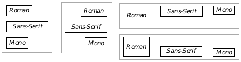
Figure 12-3 Examples of Edge Justification
From left to right (clockwise): Left justification, right justification, top justification, bottom justification.
12.2.3.2 Edge Alignment with Other Objects
HINT_ALIGN_LEFT_EDGE_WITH_OBJECT, HINT_ALIGN_TOP_EDGE_WITH_OBJECT, HINT_ALIGN_RIGHT_EDGE_WITH_OBJECT, HINT_ALIGN_BOTTOM_EDGE_WITH_OBJECT
These hints align an object’s respective edge with the same edge of another object; the optr of the other object is the hint’s argument. The other object does not necessarily have to be a direct sibling or parent, but the result must not cause the object to stray outside its parent’s bounds.
12.2.3.3 Centering Children
HINT_CENTER_CHILDREN_VERTICALLY, HINT_CENTER_CHILDREN_HORIZONTALLY
Often, rather than justifying a composite’s children, you will want to center them. These two hints allow you to center the children as shown in Figure 12-4.
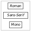
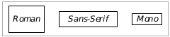
Figure 12-4 Examples of Centered Children
Vertically oriented composites may be centered horizontally; horizontally-oriented composites may be centered vertically.
12.2.3.4 Full Justification
HINT_FULL_JUSTIFY_CHILDREN_HORIZONTALLY, HINT_FULL_JUSTIFY_CHILDREN_VERTICALLY, HINT_DONT_FULL_JUSTIFY_CHILDREN, HINT_INCLUDE_ENDS_IN_CHILD_SPACING, HINT_DONT_INCLUDE_ENDS_IN_CHILD_SPACING
Besides justifying the composite’s children either on a single edge or on the center line of the composite, you might want to full-justify the children. To do this, you will want to give the composite an orientation first (either vertical or horizontal). The composite may also require a special sizing hint to expand its bounds-see HINT_EXPAND_WIDTH_TO_FIT_PARENT and the other sizing hints in section 12.2.4.
If the full justification hint is in the same dimension as the orientation of the composite (e.g., HINT_FULL_JUSTIFY_CHILDREN_HORIZONTALLY and HINT_ORIENT_CHILDREN_HORIZONTALLY), then the geometry manager will divide up the entire space of the composite and spread the children out equally along it. If you also specify HINT_INCLUDE_ENDS_IN_CHILD_SPACING, the geometry manager will calculate the spacing as if there were one more child than there actually is; it will then put half the extra space on either end of the children. HINT_DONT_INCLUDE_ENDS_IN_CHILD_SPACING performs the default calculations. Examples of various full justification are shown in Figure 12-5. See Code Display 12-3 for the code required to implement this full justification behavior.
Typically, full justification is not implemented by default. Some specific UIs may try to full-justify children always; if you want the children non-justified (when possible), apply HINT_DONT_FULL_JUSTIFY_CHILDREN. Added spacing is also typically not turned on by default; you can ensure that added spacing will not be included (where possible) by applying the hint HINT_DONT_INCLUDE_ENDS_IN_CHILD_SPACING to your composite.
12.2.4 Sizing Objects
Sizing can occur in essentially one of two ways: First, the composite can size itself based on its children. Second, the children can size themselves based on their parent. You can specify additional sizing restrictions in the form of minimum, maximum, and fixed sizes.

Figure 12-5 Full-Justification of Children
The reply bar interaction object is specified as horizontally full-justified. In the upper example, it does not include ends in child spacing; in the lower example, it does. Unchanged portions of the dialog box are cut out.
12.2.4.1 Sizing the Parent
HINT_NO_TALLER_THAN_CHILDREN_REQUIRE, HINT_NO_WIDER_THAN_CHILDREN_REQUIRE
A composite can size itself to be only as large as its children require. This may be applied to your primary window or to other organizational composites to keep them from growing into any extra space in their parents. You can set the width and height restrictions independently; to set them both, use both hints in the composite.
12.2.4.2 Sizing the Children
HINT_EXPAND_HEIGHT_TO_FIT_PARENT, HINT_EXPAND_WIDTH_TO_FIT_PARENT, HINT_DIVIDE_WIDTH_EQUALLY, HINT_DIVIDE_HEIGHT_EQUALLY
Often a composite will have a set size and its children will want to expand themselves to take up all the available space. For example, the interaction with the Apply, Reset, and Cancel triggers in the dialog box shown in Figure 12-6 must have HINT_EXPAND_WIDTH_TO_FIT_PARENT set for it to expand itself to the far right edge of the dialog box. Another potential situation is a GenView within a GenPrimary; when the user resizes the primary, the view should probably expand itself to take up any extra space in the window.

Figure 12-6 Expanding Children to Fit Parents
All the triggers in the vertical composites are expanded to fit their parents’ widths. The interaction at the bottom is as well in order to allow the triggers to be full-justified with space added.
A third example would be a series of triggers that want to be the same width in a vertical composite. This appears in many menus; each of the triggers expands itself to the width of the parent; the parent composite sizes its width to the largest of the triggers. An example taken from the complex dialog box is shown in Figure 12-6. Code for this example is shown in Code Display 12-3.
Some more complex examples of expanding a group and justifying the elements are shown in Figure 12-7. All of the examples use a justification hint combined with an expand-to-fit hint.
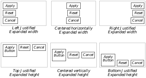
Figure 12-7 Sample Justifications
Any geometry combination can be obtained with various geometry hints and levels of organizational GenInteractions. The above six combinations apply both the expansion and the justification hints to the composite object.
Code Display 12-3 Using Full Justification of Children
/* This code display shows the basic Goc code that will get the configuration
 * shown in Figure 12-6 on the screen. Other attributes are left out of the
 * definitions of the objects. This code display is supplemental to
 * Code Display 12-2; most comments have been removed. */

@object GenInteractionClass TopInteraction = {
    GI_comp = @ParaInteraction, @ReplyInteraction;
    HINT_ORIENT_CHILDREN_VERTICALLY;
}

@object GenInteractionClass ParaInteraction = {
    GI_comp = @FontInteraction, @JustInteraction, @StyleInteraction;
    HINT_ORIENT_CHILDREN_HORIZONTALLY;
}

@object GenInteractionClass ReplyInteraction = {
    GI_comp = @ApplyTrigger, @ResetTrigger, @CancelTrigger;
    HINT_ORIENT_CHILDREN_HORIZONTALLY;
    HINT_EXPAND_WIDTH_TO_FIT_PARENT;
    HINT_FULL_JUSTIFY_CHILDREN_HORIZONTALLY;
    HINT_INCLUDE_ENDS_IN_CHILD_SPACING;
}

@object GenInteractionClass FontInteraction = {
    GI_comp = @RomanTrigger, @SansTrigger, @MonoTrigger;
    HINT_ORIENT_CHILDREN_VERTICALLY;
}

@object GenInteractionClass JustInteraction = {
    GI_comp = @LeftTrigger, @RightTrigger, @CenterTrigger, @FullTrigger;
    HINT_ORIENT_CHILDREN_VERTICALLY;
}

@object GenInteractionClass StyleInteraction = {
    GI_comp = @PlainTrigger, @BoldTrigger, @SuperTrigger, @SubTrigger;
    HINT_ORIENT_CHILDREN_VERTICALLY;
}

/* Triggers. All the upper triggers are essentially the same. Each is named as it
 * appears in the GI_comp fields above, and each has the corresponding
 * GI_visMoniker field. The RomanTrigger object is shown as an example. */

@object GenTriggerClass RomanTrigger = {
    GI_visMoniker = "Roman";
    HINT_EXPAND_WIDTH_TO_FIT_PARENT;
}

/* The Apply, Reset, and Cancel triggers do not have the hint shown above. */
@object GenTriggerClass ApplyTrigger = {
    GI_visMoniker = "Apply";
}
HINT_DIVIDE_WIDTH_EQUALLY and HINT_DIVIDE_HEIGHT_EQUALLY instruct a composite object to divide up its space along the affected dimension among the usable children. This hint can only suggest sizes for the children. The children themselves will decide if they can expand or contract to fit the requested space. (In general, children will not contract to fit a requested size, but they may expand.) Note: these hints will not work within GenValue objects; if you wish to use them on such an object, place them within a dummy GenInteraction object and use these hints on that object.
Typically, these hints work well in conjunction with HINT_EXPAND_WIDTH_TO_FIT_PARENT and HINT_EXPAND_HEIGHT_TO_FIT_PARENT. If these hints are not also in place (on a GenInteraction, for example) the division of width and/or height may be based on the children’s default size; i.e., the parent will size itself based on total size of the children and then attempt to divide up its children’s space, rather than the maximum allotted size for the parent, which is probably not desired.
12.2.4.3 Maximum, Minimum, Fixed, and Initial Sizes
HINT_INITIAL_SIZE, HINT_MAXIMINUM_SIZE, HINT_MINIMUM_SIZE, HINT_FIXED_SIZE
If you know certain sizing restrictions for window or interaction objects, you can set them with the following four hints. Each takes a parameter that details the appropriate height and width in points. The parameters are described for the hints.
HINT_INITIAL_SIZE
This hint sets the initial size of the object, if allowed. Other sizing restrictions may override this hint (such as the children being too large). This is primarily used with window objects (you will likely never use it for anything other than a GenPrimary, GenDisplay, or GenView), and it is effective only for when the object is first displayed. This hint takes an argument of type CompSizeHintArgs, a structure that defines a suggested width, height, and the number of children the object has.
HINT_FIXED_SIZE
This hint sets a fixed size for the object if one is allowed. Other sizing restrictions (such as children growing too large for the window) may override this hint occasionally. This hint can often be used for optimization to inhibit excessive geometry recalculations while on-screen. This hint takes the same parameters as HINT_INITIAL_SIZE, of type CompSizeHintArgs.
HINT_MAXIMUM_SIZE
This hint sets a desired maximum size for the object. Other geometry restrictions may override this hint when necessary. This hint is useful for GenText and GenView objects. It takes the same parameters as HINT_INITIAL_SIZE, of type CompSizeHintArgs.
HINT_MINIMUM_SIZE
This hint sets a desired minimum size for the object. Other geometry restrictions may override this hint when necessary. The hint takes the same parameters as HINT_INITIAL_SIZE, of type CompSizeHintArgs.
The following examples show different ways to set the initial size of an object. The third argument of the hint is the number of children in a particular line of a composite, when the composite is set up to wrap its children.
This example sets the initial size of the composite (probably a GenPrimary) to be half the screen’s height and half the screen’s width.
HINT_INITIAL_SIZE = {
        SST_PCT_OF_FIELD_WIDTH | PCT_50,
        SST_PCT_OF_FIELD_HEIGHT | PCT_50,
        0 };
This example sets the size of the composite to be 100 pixels high and 200 pixels wide.
HINT_FIXED_SIZE = {
        SST_PIXELS | 200,
        SST_PIXELS | 100,
        0 };
This example sets the composite’s minimum size to be 10 average characters wide and 20 percent of the screen height tall.
HINT_MINIMUM_SIZE = {
        SST_AVG_CHAR_WIDTHS | 10,
        SST_PCT_OF_FIELD_HEIGHT | PCT_20,
        0 };
12.2.5 Outlining the Composite
HINT_DRAW_IN_BOX
Often it is useful to outline a composite, especially if it is used for organizational purposes within another composite. You can use the hint HINT_DRAW_IN_BOX to have the UI automatically draw a box at the object’s bounds as shown in Figure 12-8.
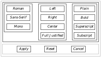
Figure 12-8 Drawing Boxes Around Composites
When HINT_DRAW_IN_BOX is used for the upper composites, the object groupings become much easier to distinguish.
12.2.6 Using Monikers
Nearly all generic objects will have visual monikers (usually text labels) that get drawn somewhere in or near the object. The moniker helps the user distinguish between different objects; for example, each trigger should have a text (or graphical) moniker giving some indication of what happens when the trigger is pressed.
12.2.6.1 Placing Monikers in Relation to Children
HINT_PLACE_MONIKER_ABOVE, HINT_PLACE_MONIKER_BELOW, HINT_PLACE_MONIKER_TO_LEFT, HINT_PLACE_MONIKER_TO_RIGHT, HINT_DO_NOT_USE_MONIKER, HINT_CENTER_MONIKER, HINT_PLACE_MONIKER_ALONG_LARGER_DIMENSION, HINT_ALIGN_LEFT_MONIKER_EDGE_WITH_CHILD
Monikers are extremely useful and dynamic-see “GenClass,” Chapter 2 of the Object Reference Book, for full information on creating, manipulating, and using visual monikers. Monikers may be created or changed at run-time (often causing geometry updates), and all generic objects may be given monikers.
If you place a composite object’s moniker to one side of its children, the geometry manager will ensure extra space in the composite gets allotted for the moniker. You can hint that the moniker should be placed above, to the right of, to the left of, or below the children. You can also hint that the moniker should not be used.
Most specific UIs will put the moniker to the left of the object’s children by default. You can also center the moniker on the composite’s children with HINT_CENTER_MONIKER. Figure 12-9 shows several different moniker placements.
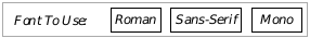
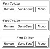
Figure 12-9 Placing Monikers
The top-left has the moniker placed to the left by default. The second uses the hint HINT_PLACE_MONIKER_ABOVE; notice that by default in this specific UI, the left moniker edge is aligned with the first child. The third also has HINT_DRAW_IN_BOX. The fourth also has the hint HINT_CENTER_MONIKER set to center the moniker.
You can also have the UI place the moniker along the object’s larger dimension-to the left if the screen is wider than it is tall, or above if the screen is taller than it is wide. To do this, set the hint HINT_PLACE_MONIKER_ALONG_LARGER_DIMENSION.
If a moniker is placed above a group of children, HINT_ALIGN_LEFT_MONIKER_EDGE_WITH_CHILD ensures that left moniker edge coincides with the left edge of the first child below that moniker. This is usually the default behavior anyway, but different specific UIs may have different default behavior.
12.2.6.2 Justifying or Centering on Monikers
HINT_CENTER_CHILDREN_ON_MONIKERS, HINT_LEFT_JUSTIFY_MONIKERS
When you have several composites within a single composite, you can center the composites based on the position and size of the monikers. Using the hint HINT_CENTER_CHILDREN_ON_MONIKERS has the effect shown in Figure 12-10: It aligns the child composites so their monikers are right-justified at the center. Adding HINT_LEFT_JUSTIFY_MONIKERS has a similar effect, except the monikers are left-justified.
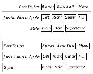
Figure 12-10 Centering on Monikers
The top composite has HINT_CENTER_CHILDREN_ON_MONIKERS set, causing the child composites to be lined up on the separation between their monikers and their children. The bottom composite also has the hint HINT_LEFT_JUSTIFY_MONIKERS as well, causing the same geometry with the addition of left-justifying the monikers.
Note that the two hints HINT_CENTER_CHILDREN_ON_MONIKERS and HINT_LEFT_JUSTIFY_MONIKERS are valid only for composites with one or more child composites, all of which have monikers placed to their left.
12.2.6.3 Removing Moniker Borders
HINT_NO_BORDERS_ON_MONIKERS
This hint removes borders that may appear by default around an object’s moniker. For example, GenTriggers under most specific UIs have a rectangular border drawn around their moniker’s borders. This hint removes these borders. It may be useful in cases where a custom border should be implemented, but in general should not be used to override the specific UI, as this may confuse the user.
12.2.7 Using Custom Child Spacing
HINT_CUSTOM_CHILD_SPACING, HINT_CUSTOM_CHILD_SPACING_IF_LIMITED_SPACE, HINT_MINIMIZE_CHILD_SPACING
Normally, spacing of children within a composite is left entirely up to the specific UI. You can customize spacing, however, by using the hint HINT_CUSTOM_CHILD_SPACING. This hint takes a single argument of type SpecSizeSpec, described below.
The SpecSizeSpec structure defines both the spacing between children and how the spacing is determined. It exists as a record with two fields: The first field is a constant of type SpecSizeTypes, used to interpret the second field. The second field is data based on the type specified in the first field.
The different types allowable in the first field are
SST_PIXELS
Data specified in pixels.
SST_PCT_OF_FIELD_WIDTH
Data specified as a percentage of screen width. The data value is a fraction that gets multiplied by the width of the screen. Predefined fraction values to use in the data field are named PCT_xx, where the xx represents any multiple of five between zero and 100 inclusive. You can get better accuracy by using your own value if desired, however.
SST_PCT_OF_FIELD_HEIGHT
Data specified as a percentage of screen height. As above except uses screen height rather than width.
SST_AVG_CHAR_WIDTHS
Data specified as a number that gets multiplied by the average width of a character in the font being used. The data may be between zero and 1023 inclusive.
SST_WIDE_CHAR_WIDTHS
Data is specified as a number that gets multiplied by the maximum width of the widest character in the font being used. The data may be between zero and 1023 inclusive.
SST_LINES_OF_TEXT
Data is specified as a number of text lines. The number will be multiplied by the height of a line of text in the font being used.
Both fields of the record are defined by using the bitwise-or operator. If you had a composite that wanted to line all its children up exactly next to each other, for example, you would specify the hint as follows:
@object GenInteractionClass @MyComp = {
    GI_comp = @child1, @child2, @child3;
    HINT_CUSTOM_CHILD_SPACING = SST_PIXELS | 0;
}
HINT_CUSTOM_CHILD_SPACING_IF_LIMITED_SPACE also takes a SpecSizeSpec to suggest a custom amount of spacing, but only implements this custom spacing if the specific UI determines that the children are already too tightly arranged. This hint may or may not be helpful, as the specific UI often allocates a minimum amount of spacing independent of this hint.
HINT_MINIMIZE_CHILD_SPACING ensures that child spacing is kept to an absolute minimum, even if this means that object’s edges will touch (in color systems) or even overlap (in black and white systems).
12.2.8 Allowing Children to Wrap
HINT_ALLOW_CHILDREN_TO_WRAP, HINT_WRAP_AFTER_CHILD_COUNT, HINT_DONT_ALLOW_CHILDREN_TO_WRAP, HINT_WRAP_AFTER_CHILD_COUNT_IF_VERTICAL_SCREEN
When a composite grows to fit its children and also must remain small enough to fit within its generic parent, it may wrap the children. This typically happens as a result of the user resizing a window smaller so the children of the composite no longer fit the window’s width. Wrapping can occur in both the horizontal and the vertical, depending on the orientation of the composite object.
To allow a composite to wrap its children when necessary, apply the hint HINT_ALLOW_CHILDREN_TO_WRAP to the composite. If you want the children not to wrap, apply HINT_DONT_ALLOW_CHILDREN_TO_WRAP. An example of wrapping children appears in Figure 12-11.

Figure 12-11 Allowing Children to Wrap
If the composite has HINT_WRAP_AFTER_CHILD_COUNT = 3, the composite will automatically wrap children after three on any given line.
When HINT_WRAP_AFTER_CHILD_COUNT is applied and children are allowed to wrap, the composite will cause its children to wrap after a certain number are displayed. This hint takes a single integer as a parameter. For example, if you wanted three children on every line in the composite no matter how many children there were total, you would specify the composite as follows:
@object GenInteractionClass @MyComp = {
    GI_comp = @child1, @child2, @child3, @child4;
    HINT_ALLOW_CHILDREN_TO_WRAP;
    HINT_WRAP_AFTER_CHILD_COUNT = 3;
}
The configuration shown above is demonstrated in Figure 12-11.
A variation, HINT_WRAP_AFTER_CHILD_COUNT_IF_VERTICAL_SCREEN, allows you to allow child wrapping based on whether or not the screen is “vertical.” If the screen is taller than it is wide, this hint will have an effect like HINT_WRAP_AFTER_CHILD_COUNT; if not, the hint will have no effect.
12.2.9 Object Placement
As we have seen, generic objects can be arranged and distributed in several ways. You may also place generic objects within certain areas of your user interface that are not explicitly defined. For example, in many dialog boxes, a “reply bar” is typically present where reply triggers such as “OK,” “Cancel,” or “Apply” are located. You may specify objects to generically place themselves within such a reply bar, even though you may not know the exact location of that reply bar as the specific UI creates it.
12.2.9.1 Reply Bars
HINT_MAKE_REPLY_BAR, HINT_SEEK_REPLY_BAR
One special feature that many dialog boxes have is a reply bar. Typically, any dialog box that allows the user to set a number of options before applying them will have a reply bar. A reply bar usually has triggers in it for “Apply,” “Cancel,” and perhaps other functions (such as “Reset”).
Note that many special dialog box types can have their reply bars built automatically according to the specific UI. See “GenInteraction,” Chapter 7 of the Object Reference Book, for full information on reply bars. If you want to create your own, however, you can with the hints in this section.
Although you have to declare each of the triggers that will appear in the reply bar, you can use HINT_MAKE_REPLY_BAR to set up the geometry appropriate for the specific UI. For example, Code Display 12-4 gives the code that will create a reply bar similar to that shown in Figure 12-12.

Figure 12-12 Implementations of a Reply Bar
The specific UI determines the actual geometry of the reply bar including justification, sizing, and other features.
Code Display 12-4 Creating a Reply Bar
/* This reply bar has three triggers, Apply, Reset, and Cancel. A few possible
 * formats determined by the specific UI are shown in Figure 12-12. The
 * appropriate geometry is not determined until run-time. */

@object GenInteractionClass MyReplyBar = {
    GI_comp = @ApplyTrigger, @ResetTrigger, @CancelTrigger;
    HINT_MAKE_REPLY_BAR;
}

@object GenTriggerClass ApplyTrigger = {
    GI_visMoniker = "Apply"; }

@object GenTriggerClass ResetTrigger = {
    GI_visMoniker = "Reset"; }

@object GenTriggerClass CancelTrigger = {
    GI_visMoniker = "Cancel"; }
HINT_SEEK_REPLY_BAR instructs the generic object (usually a GenTrigger) to seek placement in the dialog box’s reply bar. The specific UI will try to place the trigger in the reply bar of the first dialog box GenInteraction it finds that is not GIT_ORGANIZATIONAL.
12.2.9.2 Placing Objects in Menu Bars
HINT_SEEK_MENU_BAR, HINT_AVOID_MENU_BAR
Usually, it is left up to the specific UI whether it places any given object within a menu bar. You can suggest that objects be placed within the window’s menu bar by placing HINT_SEEK_MENU_BAR on that object. Similarly, you can place HINT_AVOID_MENU_BAR on an object to suggest that it not be placed within the window’s menu bar.
12.2.9.3 Placing Objects in Scroller Areas
HINT_SEEK_X_SCROLLER_AREA, HINT_SEEK_Y_SCROLLER_AREA, HINT_SEEK_LEFT_OF_VIEW, HINT_SEEK_TOP_OF_VIEW, HINT_SEEK_RIGHT_OF_VIEW, HINT_SEEK_BOTTOM_OF_VIEW
These hints affect the placement of generic objects within GenViews. The objects must be children of a GenView for the hints to take effect.
HINT_SEEK_X_SCROLLER_AREA and HINT_SEEK_Y_SCROLLER_AREA suggest that a generic object be placed alongside the scrollbar area-either the horizontal scrollbar or the vertical scrollbar, respectively-of the GenView object.
HINT_SEEK_LEFT_OF_VIEW, HINT_SEEK_TOP_OF_VIEW, HINT_SEEK_RIGHT_OF_VIEW and HINT_SEEK_BOTTOM_OF_VIEW suggest that the generic object be placed alongside the respective side of the GenView.
12.2.9.4 Placing Objects in Window Title Bars
HINT_SEEK_TITLE_BAR_LEFT, HINT_SEEK_TITLE_BAR_RIGHT
These hints suggest the placement of a generic object within a window’s title bar. These hints are usually used on GenTriggers or GenInteractions; the objects involved should fit within the title bar area (i.e., be equivalent to tool bar icons). For each window with a title bar, only one object may have each of these hints, and the object must be a direct child of the windowed object.
12.2.9.5 Placement of Objects Popped Up
HINT_POPS_UP_TO_RIGHT, HINT_POPS_UP_BELOW
HINT_POPS_UP_TO_RIGHT This hint instructs the specific UI to bring up the object to the right of its activating gadget, if the object is normally popped up below the activating gadget.
HINT_POPS_UP_BELOW This hint instructs the specific UI to bring up the object below its activating gadget. This is usually the default behavior for objects that are popped up.
12.3 Positioning and Sizing Windows
A generic object that appears as a window, such as an independently-displayable GenInteraction or a GenPrimary, has special needs for positioning and sizing itself, especially when appearing initially. Specific user interfaces may differ in how windows appear on the screen. In Motif, for instance, windows initially appear in one of several staggered positions. Primary and display objects extend by default to the right edge of the screen and to the top edge of the icon area at the bottom of the screen. Other windows are usually only as large as required by their children.
The SpecSizeWinPair structure is often used when specifying window sizes and positions. There are several hints which signal that a window should be positioned or sized depending on the position or size of another window, the size of the screen, or other conditions. The SpecSizeWinSpec structure allows you to specify an offset from another window, either by a number of points (remember that there are 72 points per inch), or by means of a ratio.
typedef struct {
        SpecWinSizeSpec                 SWSP_x;
        SpecWinSizeSpec                 SWSP_y;
} SpecWinSizePair;

typedef WordFlags SpecWinSizeSpec;
#define SWSS_RATIO                              0x8000
#define SWSS_SIGN                               0x4000
#define SWSS_MANTISSA                           0x3c00
#define SWSS_FRACTION                           0x03ff
The SpecSizeWinPair structure allows you to set up separate parameters for the x and y coordinates. For each coordinate, use the SWSS_RATIO flag to signal whether you are giving coordinates by means of a ratio instead of a constant. If you are using a ratio, use the SWSS_FRACTION, SWSS_MANTISSA, and SWSS_SIGN fields to specify the value of the ratio or use one of the following pre-defined constants to specify a ratio between zero and one:
#define PCT_0                   0x000
#define PCT_5                   0x033
#define PCT_10                  0x066
#define PCT_15                  0x099
#define PCT_20                  0x0cc
#define PCT_25                  0x100
#define PCT_30                  0x133
#define PCT_35                  0x166
#define PCT_40                  0x199
#define PCT_45                  0x1cc
#define PCT_50                  0x200
#define PCT_55                  0x233
#define PCT_60                  0x266
#define PCT_65                  0x299
#define PCT_70                  0x2cc
#define PCT_75                  0x300
#define PCT_80                  0x333
#define PCT_85                  0x366
#define PCT_90                  0x399
#define PCT_95                  0x3cc
#define PCT_100                 0x3ff
To specify a constant offset, just use that offset, not setting the SWSS_RATIO flag. Not all windows will use the SpecWinSizePair structure.
12.3.1 Window Positioning
HINT_POSITION_WINDOW_AT_RATIO_OF_PARENT, HINT_POSITION_WINDOW_AT_MOUSE, HINT_STAGGER_WINDOW, HINT_CENTER_WINDOW, HINT_TILE_WINDOW, HINT_WINDOW_NO_CONSTRAINTS
GenClass has a number of hints used by the window classes to determine where the window appears initially and how the window is allowed to move about the screen. Specific UIs can override these hints when necessary or when they conflict with the UI’s specifications. These hints are listed below.
HINT_POSITION_WINDOW_AT_RATIO_OF_PARENT
This hint suggests an initial position for the window based on its parent window’s size and relative to the upper-left corner of the parent window. The suggested position is specified as a fraction of the parent window’s size in a SpecWinSizePair structure. This structure consists of two fields, the X position and the Y position of the new window’s origin. Predetermined fraction values are names PCT_xx, where xx is a multiple of five between zero and 100 inclusive. For example, to have the window object’s origin start out in the center of its parent, specify the hint as follows:
HINT_POSITION_WINDOW_AT_RATIO_OF_PARENT = {
    SWSS_RATIO | PCT_25, SWSS_RATIO | PCT_60
};
HINT_POSITION_WINDOW_AT_MOUSE
This hint will position the origin of the new window at the mouse pointer.
HINT_STAGGER_WINDOW
This hint indicates that the window’s origin should be placed just below and to the right of the origin of the last staggered window.
HINT_CENTER_WINDOW
This hint centers the window in its parent window.
HINT_TILE_WINDOW
This hint tiles the window with other windows that are also marked HINT_TILE_WINDOW within the parent window. This hint is not currently supported.
HINT_WINDOW_NO_CONSTRAINTS
This hint removes all constraints upon the positioning of a window. It should only be used as the final attempt to position the window if other methods do not work to your satisfaction.
12.3.2 Determining Initial Size
HINT_EXTEND_WINDOW_TO_BOTTOM_RIGHT, HINT_EXTEND_WINDOW_NEAR_BOTTOM_RIGHT, HINT_SIZE_WINDOW_AS_DESIRED, HINT_SIZE_WINDOW_AS_RATIO_OF_PARENT, HINT_SIZE_WINDOW_AS_RATIO_OF_FIELD, HINT_USE_INITIAL_BOUNDS_WHEN_RESTORED
GenClass has a number of hints used by the window classes to determine the size of the window object initially and how the window is allowed to be resized on the screen. Specific UIs can override these hints when necessary or when they conflict with the UI’s specifications. These hints are listed below.
HINT_EXTEND_WINDOW_TO_BOTTOM_RIGHT
This hint extends the window’s bounds so its lower right corner is located at the lower right corner of its parent window.
HINT_EXTEND_WINDOW_NEAR_BOTTOM_RIGHT
This hint extends the window’s bounds so its lower right corner is located near the lower right corner of its parent window. Enough room will be left for any icon area that may be present. Most major applications will apply this hint to their GenPrimary objects.
HINT_SIZE_WINDOW_AS_DESIRED
This hint allows the window to size itself according to the combined size of its children.
HINT_SIZE_WINDOW_AS_RATIO_OF_PARENT
This hint sizes the window to a ratio of its parent window. It takes a single parameter of type SpecWinSizePair, described under HINT_POSITION_WINDOW_AT_RATIO_OF_PARENT. Instead of coordinates, however, the ratios in the structure are width and height.
HINT_SIZE_WINDOW_AS_RATIO_OF_FIELD
This hint sizes the window to a ratio of the field window’s size. It takes a SpecWinSizePair parameter indicating the ratio. See above.
HINT_USE_INITIAL_BOUND_WHEN_RESTORED
This hint instructs the window to come on-screen with its original values rather than the state of the window when it was saved to state.
12.3.3 On-Screen Behavior
HINT_KEEP_INITIALLY_ONSCREEN, HINT_DONT_KEEP_INITIALLY_ONSCREEN, HINT_KEEP_PARTIALLY_ONSCREEN, HINT_DONT_KEEP_PARTIALLY_ONSCREEN, HINT_KEEP_ENTIRELY_ONSCREEN, HINT_KEEP_ENTIRELY_ONSCREEN_WITH_MARGIN, HINT_NOT_MOVABLE
HINT_KEEP_INITIALLY_ONSCREEN
This hint will make the window resize itself to fit entirely within its parent window. Most windows will inherently know how to come up fully on-screen; some specific UIs do not implement it by default for optimization purposes.
HINT_DONT_KEEP_INITIALLY_ONSCREEN
This hint will allow the window to come up whether it will be fully on-screen or not. If the default is to keep the window entirely on-screen and the UI allows this hint, the window will be allowed to open partially off-screen.
HINT_KEEP_PARTIALLY_ONSCREEN
This hint indicates that when the user moves the window, it will be forced to remain partially on-screen.
HINT_DONT_KEEP_PARTIALLY_ONSCREEN
This hint indicates that the user can move the window around the screen at will, even if the window becomes completely obscured under its parent.
HINT_KEEP_ENTIRELY_ONSCREEN
This hint indicates that when the user moves the window, it will be forced to remain entirely on-screen.
HINT_KEEP_ENTIRELY_ONSCREEN_WITH_MARGIN
This hint indicates that when the user moves the window, it will be forced to remain on-screen. An additional margin is added to the edge of the screen to keep the window from touching the edge as well; this margin is defined by the specific UI.
HINT_NOT_MOVABLE
This hint instructs the specific UI to make the windowed object not movable. This hint should be avoided if at all possible.
12.3.4 Window Look and Feel
HINT_WINDOW_NO_TITLE_BAR, HINT_WINDOW_NO_SYS_MENU
HINT_WINDOW_NO_TITLE_BAR instructs the specific UI to remove the title bar from a windowed object (dialog box, GenPrimary or GenDisplay). Use this hint with extreme prejudice as most of a window’s functionality will not be accessible without a title bar.
HINT_WINDOW_NO_SYS_MENU instructs the specific UI to remove the system menu (or close button) from a windowed object. Again, do not use this hint unless necessary, as it overrides important features of windowed objects.