19 Ruler Object Library
The ruler library provides objects that act as rulers. These rulers may be linked up with a GenView object so that when the user scrolls around within the GenView, the rulers update accordingly. The rulers work with a variety of measurement systems and also provide grids and guidelines to help the user to figure out the spacial layout of a graphic space. To aid the user’s mouse movement, the rulers can constrain the mouse’s movement to certain lines.
To work with the basic ruler set-up, you don’t need to know much about GEOS other than the basics of objects and messaging. However, for certain customizations, you will probably need to know something about GenViews and notifications they pass on to linked objects.
19.1 Ruler Features
Rulers are a “must have” feature for drawing programs or any geode concerned with layout-intensive tasks. By alerting the rulers to pointer events, the application may display marks in the ruler which track the mouse’s position so that the user knows the exact mouse coordinates. The ruler library provides many more features to applications prepared to support those features:
Grids
The ruler’s tick marks are of course drawn inside the ruler. However, the ruler can draw a grid over the main view so that the user may see where major units fall on the document directly.Guides
While a regular grid is helpful, the user may want to set up guidelines to mark off areas important to a document’s layout. These guides may appear both as marks on the ruler and lines across the main view itself.Mouse Constraints
The rulers can act as mouse constraint managers. The mouse location can snap to grid lines, guidelines, or lines at any angle through any point.Large Document Support
The rulers work with large (32-bit) documents. They respond correctly to large mouse and scrolling events. However, at this time there is no way using C to intercept the message by which the Ruler handles large pointer events.Controller Support
The ruler library includes a full suite of controller objects, including controllers for managing grids and guides.
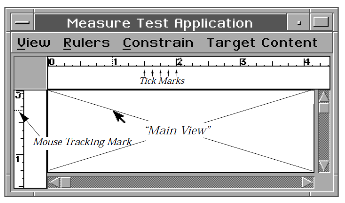
Figure 19-1 Rulers
19.2 Ruler Setup
For each ruler a geode displays, it will need to include three objects: an object of RulerViewClass to display the ruler, a RulerContentClass object to act as the top of the RulerView’s visible tree, and a VisRulerClass object, the ruler itself. Also, the geode may wish to include some of the available ruler control objects.
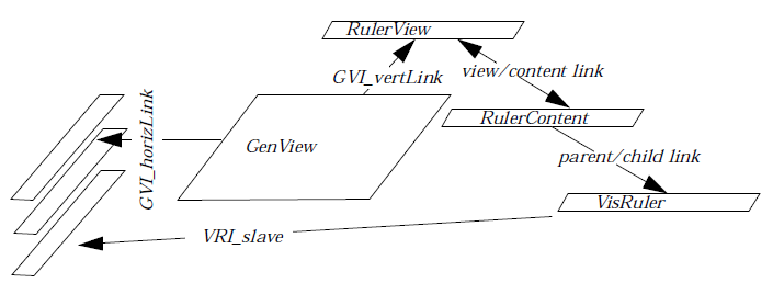
Figure 19-2 UI Linkages for Rulers
The RulerViews should be alerted when the main GenView scrolls or scales, so set the GenView’s GVI_horizLink and GVI_vertLinks to hold the optrs of the RulerViews. A RulerView to the side of the GenView should be linked by the horizontal link; a RulerView above or below the GenView should be linked vertically.
Each RulerView should have a RulerContent as its content. Set this up as you would a normal GenView/VisContent linkage. The RulerContent functions as a VisContent for most purposes; there is some subclassed behavior so that the VisRuler will be notified when the RulerView has detected a scroll or scale event.
A VisRuler should be the child of the RulerContent. If you have more than one VisRuler associated with a view, you should use the VRI_slave links to connect them. When one VisRuler receives certain messages, it will handle them and pass them on to whatever VisRuler has been designated in its VRI_slave field. If this slave ruler itself has a slave, then the message will be relayed again, and so on. Thus the application only has to send messages to one ruler, instead of to all of them. The ruler which is not the target of a VRI_slave link is the view’s master ruler, and its VRA_MASTER bit should be set.
If the view only has one ruler associated with it, that ruler’s VRA_MASTER bit should be set.
If you will use the ruler library’s mouse constraint management support, then the VisRulers must be run in the same thread which manages the main content. The VisRuler messages which deal with mouse positions receive the mouse location parameters on the stack, and thus the handlers must be running in the same thread as the callers. This is not a major restriction: since mouse events are so common, sending them across threads to be processed would lead to slow, jerky responses.
Your application may also include other objects:
RulerTypeControl to allow the user to use different measurement units.
RulerGridControl to draw a grid on the main view to which the user may snap the mouse.
RulerGuideControl to allow the user to manage guidelines.
RulerShowControl to show or hide rulers. Because hidden rulers are set not usable, and thus do not work well with GCN, applications including a RulerShowControl need to do some extra work. This is not difficult, but exactly what needs to be done may vary between applications. For details, see Section 19.4.1 below.
If you will be using any of the ruler controllers, you must provide a way to relay classed events to the VisRuler objects. Whichever object will have the target when the controllers send out their classed events must have a special handler for MSG_META_SEND_CLASSED_EVENT which determines if the message is intended for a member of VisRuler class, and if so passes it to the master VisRuler object. Note that if you are working with the grobj library, a targeted GrObjBody correctly relays classed events to rulers.
Finally, if you wish the VisRuler to take special action on certain mouse events (perhaps providing a mark on the ruler to track the mouse pointer’s position), the GenView’s content should intercept those mouse events and send messages to the VisRuler (again, the VisRuler at the top of the VRI_slave chain) with the requested action.
19.3 VisRuler Instance Data
The VisRuler’s instance data fields are listed below. Depending on your setup, the management of most of these fields will probably be taken care of by the ruler itself or some of its associated controllers. However, many programs set values for the VRI_rulerAttrs, VRI_constrainStrategy, and VRI_slave fields when defining their rulers.
Code Display 19-1
@classVisRulerClass,VisClass;
@instance VisRulerAttributes VRI_rulerAttrs;

typedef ByteFlags VisRulerAttributes;
#define VRA_IGNORE_ORIGIN       0x80
#define VRA_SHOW_GUIDES         0x40
#define VRA_SHOW_GRID           0x20
#define VRA_SHOW_MOUSE          0x10
#define VRA_HORIZONTAL          0x08
#define VRA_MASTER              0x04

@instance VisRulerType VRI_type;

typedef ByteEnum VisRulerType;
#define VRT_INCHES          0x0
#define VRT_CENTIMETERS     0x1
#define VRT_POINTS          0x2
#define VRT_PICAS           0x3
#define VRT_CUSTOM          CUSTOM_RULER_DEFINITION
#define VRT_NONE            NO_RULERS
#define VRT_DEFAULT         SYSTEM_DEFAULT

@instance VisRulerConstrainStrategy VRI_constrainStrategy;

typedef WordFlags VisRulerConstrainStrategy;
#define VRCS_OVERRIDE                               0x8000
#define VRCS_SET_REFERENCE                          0x2000
#define VRCS_SNAP_TO_GRID_X_ABSOLUTE                0x1000
#define VRCS_SNAP_TO_GRID_Y_ABSOLUTE                0x0800
#define VRCS_SNAP_TO_GRID_X_RELATIVE                0x0400
#define VRCS_SNAP_TO_GRID_Y_RELATIVE                0x0200
#define VRCS_SNAP_TO_GUIDES_X                       0x0100
#define VRCS_SNAP_TO_GUIDES_Y                       0x0080
#define VRCS_CONSTRAIN_TO_HORIZONTAL_AXIS           0x0040
#define VRCS_CONSTRAIN_TO_VERTICAL_AXIS             0x0020
#define VRCS_CONSTRAIN_TO_UNITY_SLOPE_AXIS          0x0010
#define VRCS_CONSTRAIN_TO_NEGATIVE_UNITY_SLOPE_AXIS 0x0008
#define VRCS_CONSTRAIN_TO_VECTOR                    0x0004
#define VRCS_CONSTRAIN_TO_VECTOR_REFLECTION         0x0002
#define VRCS_INTERNAL                               0x0001

@instance MinIncrementType  VRI_minIncrement; /* minimum increment displayed */

typedef union {
    MinUSMeasure            MIT_US;
    MinMetricMeasure        MIT_METRIC;
    MinPointMeasure         MIT_POINT;
    MinPicaMeasure          MIT_PICA;
} MinIncrementType;

typedef ByteEnum MinUSMeasure;
#define MUSM_EIGHTH_INCH            0x0
#define MUSM_QUARTER_INCH           0x1
#define MUSM_HALF_INCH              0x2
#define MUSM_ONE_INCH               0x3

typedef ByteEnum MinMetricMeasure;
#define MMM_MILLIMETER              0x0
#define MMM_HALF_CENTIMETER             0x1
#define MMM_CENTIMETER              0x2

typedef ByteEnum MinPointMeasure;
#define MPM_25_POINT                0x0
#define MPM_50_POINT                0x1
#define MPM_100_POINT               0x2

typedef ByteEnum MinPicaMeasure;
#define MPM_PICA                0x0
#define MPM_INCH                0x1

@instance WWFixed VRI_scale; /* scale factor */

@instance DWFixed VRI_origin; /* 0,0 of the ruler in document coordinates */

@instance PointDWFixed VRI_reference;

@instance sdword VRI_mouseMark;

@instance word VRI_window; /* actually a noreloc WindowHandle */

@instance optr VRI_slave;

@instance Grid VRI_grid;

@instance WWFixed VRI_vectorSlope; /* slope of vector */

@instance optr VRI_guideArray;

@instance word VRI_guideInfluence; /* influence of guides in pixels */

@instance word VRI_desiredSize;

@instance word VRI_reserved;

@instance dword VRI_invalOD; /* actually a noreloc optr */

@instance word VRI_transformGState; /* actually a noreloc GStateHandle */
The VRI_rulerAttrs field contains flags which determine whether the ruler will support given features. This field tends to vary between applications; put some thought into which flags to turn on.
VRA_IGNORE_ORIGIN
Using the VRI_origin field, it is possible to set an origin for the user to use based upon the coordinates of the graphic space within the main view. This can come in handy when the zero point for the ruler shouldn’t correspond to the very left or top of the view; GeoWrite uses this when the user wants the ruler’s origin to be based upon the right edge of a text object rather than the edge of the view. The VRA_IGNORE_ORIGIN flag effectively turns off this feature.
VRA_SHOW_GUIDES
This flag indicates that the user wants guidelines drawn over their main view.
VRA_SHOW_GRID
This flag indicates that the user wants gridlines drawn over the main view.
VRA_SHOW_MOUSE
This flag indicates that the ruler should draw a tick mark to show the mouse pointer’s location.
VRA_HORIZONTAL
This flag indicates that the ruler is horizontal. Horizontal rulers should have this flag turned on; vertical rulers should not.
VRA_MASTER
If a given view has only one ruler associated with it, that ruler should have this flag set. If a given view has more than one ruler (perhaps having one horizontal and one vertical), one of these rulers should be set up as the master ruler. It should have the VRA_MASTER flag set and should have the second ruler’s optr in its VRI_slave field. If there is a third ruler, the second ruler should have its optr in its (the second ruler’s) VRI_slave field, and so on.
The VRI_constrainStrategy field contains the default mouse constraint strategy the ruler should use when constraining mouse movement.
VRCS_OVERRIDE
This flag isn’t really meant to be part of the default mouse constraint; it will be ignored if in the VRI_constrainStrategy field. During some events other constrain strategies may be combined with the default mouse constrain strategy; if the other strategy’s VRCS_OVERRIDE flag is set, then the default mouse constraint strategy field will be ignored.
VRCS_SET_REFERENCE
This flag signals that the next selection should signal that the user wishes the point clicked on to be the reference point, which is used with certain kinds of mouse constraint.
VRCS_SNAP_TO_GRID_X_ABSOLUTE
This flag signals that the mouse position should be snapped to the grid horizontally.
VRCS_SNAP_TO_GRID_Y_ABSOLUTE
This flag signals that the mouse position should be snapped to the grid vertically.
VRCS_SNAP_TO_GRID_X_RELATIVE
This flag signals that the mouse position should be horizontally snapped to a grid such as would be formed if the present grid spacing was used with the reference point as the grid’s origin.
VRCS_SNAP_TO_GRID_Y_RELATIVE
This flag signals that the mouse position should be vertically snapped to a grid such as would be formed if the present grid spacing was used with the reference point as the grid’s origin.
VRCS_SNAP_TO_GUIDES_X
This flag signals that the mouse positions should be horizontally snapped to guidelines. Note that guidelines are only effective within range of their “influence” in pixels.
VRCS_SNAP_TO_GUIDES_Y
This flag signals that the mouse positions should be vertically snapped to guidelines. Note that guidelines are only effective within range of their “influence” in pixels.
VRCS_CONSTRAIN_TO_HORIZONTAL_AXIS
This flag signals that the mouse position should be restrained to the horizontal line passing through the reference point.
VRCS_CONSTRAIN_TO_VERTICAL_AXIS
This flag signals that the mouse position should be restrained to the vertical line passing through the reference point.
VRCS_CONSTRAIN_TO_UNITY_SLOPE_AXIS
This flag signals that the mouse position should be restrained to the diagonal line with slope (y = x) passing through the reference point.
VRCS_CONSTRAIN_TO_NEGATIVE_UNITY_SLOPE_AXIS
This flag signals that the mouse position should be restrained to the diagonal line with slope (y = -x) passing through the reference point.
VRCS_CONSTRAIN_TO_VECTOR
This flag signals that the mouse position should be constrained to the line passing through the reference and vector points.
VRCS_CONSTRAIN_TO_VECTOR_REFLECTION
This flag signals that the mouse position should be constrained to the reflection of the line passing through the reference and vector points.
The VRI_type and VRI_minIncrement fields determine the measurement type and ruler increment of the ruler.Normally, the user will work with the ruler’s type via a RulerTypeControl. RulerTypeControlClass’s features structures are shown below.
Code Display 19-2 RulerTypeControl Features
typedef WordFlags RTCFeatures;
#define RTCF_DEFAULT            (0x20)
#define RTCF_SPREADSHEET        (0x10)
#define RTCF_INCHES             (0x08)
#define RTCF_CENTIMETERS        (0x04)
#define RTCF_POINTS             (0x02)
#define RTCF_PICAS              (0x01)
#define RTC_DEFAULT_FEATURES \
    (RTCF_INCHES | RTCF_CENTIMETERS | RTCF_POINTS | RTCF_PICAS | RTCF_DEFAULT)

typedef WordFlags RTCToolboxFeatures;
#define RTCTF_DEFAULT               (0x20)
#define RTCTF_SPREADSHEET           (0x10)
#define RTCTF_INCHES                (0x08)
#define RTCTF_CENTIMETERS           (0x04)
#define RTCTF_POINTS                (0x02)
#define RTCTF_PICAS                 (0x01)
#define RTC_DEFAULT_TOOLBOX_FEATURES (RTCF_INCHES | RTCF_CENTIMETERS)
The RulerTypeControl uses a notification block with the following structure:
typedef struct RulerTypeNotificationBlock {
    VisRulerType RTNB_type;
} RulerTypeNotificationBlock;
The ruler must keep track of the main view’s scale; if the main view has doubled in scale, the ruler should put its tick marks twice as far apart. This scale is stored in the VRI_scale field. The ruler automatically receives a MSG_VIS_RULER_VIEW_SCALE_FACTOR_CHANGED when the main view’s scale changes. To set the scale independently of the main view scale, send a MSG_VIS_RULER_SET_SCALE.
The VRI_origin field allows you to set an origin for the ruler other than (0,0). The coordinates are given in terms of the main view’s coordinate system.
The reference point, used for various types of mouse constraint, is stored in the VRI_reference field.
VRI_mouseMark contains the coordinate at which the mouse tick is currently being drawn.
The VRI_window field, initiated automatically, holds the window handle of the main view.
The VRI_slave field holds the ruler’s slave ruler; see the documentation for VRA_MASTER, above, to learn about master and slave rulers.
The VRI_grid field contains the information used to maintain the grid associated with a ruler.
The VRI_vectorSlope defines the slope of a vector that may be used with vector mouse constraints.
The VRI_guideArray field keeps track of the location where guideline data is stored; this field is initiated automatically.
The VRI_guideInfluence contains the influence to use when constraining the mouse position to guidelines. Guidelines will only attract the mouse if it is within a certain distance of them - this distance is the “influence” of the guidelines. It is measured in pixels, not points; thus, the guide influence is independent of scale.
The VRI_desiredSize field contains the ruler’s idea of its ideal thickness. By default, this is set so that the ruler will have room to draw its numbers and tick marks normally; if you will be subclassing the VisRuler to add more gadgetry, you may wish to use a different value here.
The VRI_invalOD field contains the object descriptor of the object which should be redrawn when the ruler needs to draw something differently to the main view; by the ruler’s default behavior, this will be updated automatically via a MSG_VIS_RULER_GAINED_SELECTION.
The VRI_transformGState field contains the handle of a GState. This GState contains the transformation which is used to transform the coordinate system used with mouse constraints.
MSG_VIS_RULER_SET_TYPE
void    MSG_VIS_RULER_SET_TYPE(
        VisRulerType type);
This message sets the VRI_type field.
MSG_VIS_RULER_GET_TYPE
VisRulerType MSG_VIS_RULER_GET_TYPE();
This message returns the value in the VRI_type field.
MSG_VIS_RULER_SET_CONSTRAIN_STRATEGY
void    MSG_VIS_RULER_SET_CONSTRAIN_STRATEGY(
        VisRulerConstrainStrategy       setflags,
        VisRulerConstrainStrategy       clearflags);
This message sets the default mouse constrain strategy for the ruler.
Parameters:
setflags - Flags to set.
clearflags - Flags to clear.
Return: Nothing.
MSG_VIS_RULER_GET_CONSTRAIN_STRATEGY
VisRulerConstrainStrategy MSG_VIS_RULER_GET_CONSTRAIN_STRATEGY();
This message gets the current default constrain strategy for the ruler.
MSG_VIS_RULER_SET_IGNORE_ORIGIN
void    MSG_VIS_RULER_SET_IGNORE_ORIGIN(
        Boolean         ignore);
This message sets the “ignore origin” state.
Parameters:
ignore - Set true (i.e. non-zero) to ignore the origin. Set false (i.e. zero) not to ignore the origin.
Return: Nothing.
MSG_VIS_RULER_SET_ORIGIN
void    MSG_VIS_RULER_SET_ORIGIN(
        sdword      pointInt,
        word        pointFrac);
Use this message to set the ruler’s origin point.
MSG_VIS_RULER_GET_ORIGIN
void    MSG_VIS_RULER_GET_ORIGIN(
        DWFixedReturn *retval);
Use this message to retrieve the ruler’s origin point.
Structures:
typedef struct {
    word        unused;
    word        DWFR_frac;
    sdword      DWFR_int;
} DWFixedReturn;
MSG_VIS_RULER_SET_REFERENCE
void    MSG_VIS_RULER_SET_REFERENCE( @stack
        sdword      yInt,
        word        yFrac,
        sdword      xInt,
        word        xFrac);
Set the ruler’s reference point.
MSG_VIS_RULER_SET_VECTOR
void    MSG_VIS_RULER_SET_VECTOR( @stack
        sdword      yInt,
        word        yFrac,
        sdword      xInt,
        word        xFrac);
Set the point to use to define the “vector”-together with the reference point, this will form a slope which may be used for mouse constraints.
MSG_VIS_RULER_SET_MIN_INCREMENT
void    MSG_VIS_RULER_SET_MIN_INCREMENT(
        MinIncrementType min);
This message sets the VRI_minIncrement field to the passed value. It must be passed the proper MinIncrementType value.
MSG_VIS_RULER_SET_SCALE
void    MSG_VIS_RULER_SET_SCALE(
        WWFixedAsDWord scale);
This message sets the VRI_scale field.
19.4 Managing Rulers
Most ruler functions will happen automatically. However, certain pieces of functionality require that the geode provide certain message handlers. Some geodes may have use for subclassed ruler objects, and subclassing will require further extra code. This section provides information for those who would learn more about how to manage rulers.
19.4.1 RulerShowControl
The RulerShowControl allows the user to show or hide rulers. This control works by setting RulerViews not usable. However, objects which aren’t usable don’t work with GCN, and thus you will need to set up some other object to intercept the appropriate notifications. Don’t try to include a RulerShowControl unless you know about GCN or are willing to learn.
When declaring your RulerShowControl, you may choose a GCN list which the control will work with. The default list is MANUFACTURER_ID_GEOWORKS: GAGCNLT_DISPLAY_OBJECTS_WITH_RULERS. However, you may change this to be any list you like. You must also specify a message which some object will respond to.
Some object which will be usable when the user has access to the RulerShowControl should be on the control’s GCN list. This object must be prepared to handle the message in the RSCI_message field. This message should take a RulerShowControlAttributes structure and set the ruler views usable or not usable accordingly. See Code Display 19-4 for an example.
Code Display 19-3 RulerShowControl Instance Data and Features
typedef WordFlags RSCCFeatures;
#define RSCCF_SHOW_VERTICAL     (0x04)
#define RSCCF_SHOW_HORIZONTAL   (0x02)
#define RSCCF_SHOW_RULERS       (0x01)

typedef WordFlags RSCCToolboxFeatures;
/* There are no toolbox features. */

#define RSCC_DEFAULT_FEATURES (RSCCF_SHOW_VERTICAL | RSCCF_SHOW_HORIZONTAL)
#define RSCC_DEFAULT_TOOLBOX_FEATURES (0)

@instance RulerShowControlAttributes            RSCI_attrs;
typedef WordFlags RulerShowControlAttributes;
#define RSCA_SHOW_VERTICAL              0x8000
#define RSCA_SHOW_HORIZONTAL            0x4000

@instance GCNListType           RSCI_gcnList; /* object to notify */

@instance Message               RSCI_message; /* message to notify with */
Code Display 19-4 Sample Handler for use with RulerShowControl
@method MyDisplayClass, MSG_MD_UPDATE_RULERS{
    /* The RulerShowControl's RSCI_message field should be
     * MSG_MD_UPDATE_RULERS. The message should have been declared
     * using the RULER_SHOW_CONTROL_NOTIFY prototype. */

    if (attrs & RSCA_SHOW_VERTICAL) {
        @call LeftView::MSG_GEN_SET_USABLE(VUM_NOW);
    }
     else {
        @call LeftView::MSG_GEN_SET_NOT_USABLE(VUM_NOW);
    }
    if (attrs & RSCA_SHOW_HORIZONTAL) {
        @call TopView::MSG_GEN_SET_USABLE(VUM_NOW);
    }
    else {
        @call TopView::MSG_GEN_SET_NOT_USABLE(VUM_NOW);
    }
}
19.4.2 Mouse Tracking
The ruler has the ability to show a tick mark which tracks the mouse’s movement. This can be a boon to users who wish to know the mouse’s precise location.
MSG_VIS_RULER_SHOW_MOUSE
void MSG_VIS_RULER_SHOW_MOUSE();
Sets a flag such that the ruler will draw the mouse tick on pointer events.
MSG_VIS_RULER_HIDE_MOUSE
void MSG_VIS_RULER_HIDE_MOUSE();
Sets a flag such that the ruler won’t draw the mouse tick on pointer events.
MSG_VIS_RULER_DRAW_MOUSE_TICK
void    MSG_VIS_RULER_DRAW_MOUSE_TICK( @stack
        sdword      yInt,
        word        yFrac,
        sdword      xInt,
        word        xFrac);
This message indicates that the ruler should draw a line indicating the mouse position and informs the ruler of the mouse’s new position.
19.4.3 Grid Spacing and Constraint
Applications which provide rulers often do so to allow the user to work with the mouse more accurately. Such applications might also provide a grid. A grid helps locate the mouse pointer’s exact location on the document without the need to watch the ruler. The ruler can also constrain mouse movement to the grid.
To allow the user to change the grid spacing, include a RulerGridControl. The features structures for the RulerGridControl are shown below.
Code Display 19-5 RulerGridControlClass Features
typedef WordFlags RGCFeatures;
#define RGCF_GRID_SPACING           (0x04)
#define RGCF_SNAP_TO_GRID           (0x02)
#define RGCF_SHOW_GRID              (0x01)

#define RGC_DEFAULT_FEATURES \
        (RGCF_GRID_SPACING | RGCF_SNAP_TO_GRID | RGCF_SHOW_GRID)

#define RGC_DEFAULT_TOOLBOX_FEATURES (0)
MSG_VIS_RULER_SHOW_GRID
void MSG_VIS_RULER_SHOW_GRID();
Use this message to request that the grid be drawn to the main view, setting the VRA_SHOW_GRID flag.
MSG_VIS_RULER_HIDE_GRID
void MSG_VIS_RULER_HIDE_GRID();
Use this message to request that the grid not be drawn to the main view, clearing the VRA_SHOW_GRID flag.
MSG_VIS_RULER_DRAW_GRID
void    MSG_VIS_RULER_DRAW_GRID(
        GStateHandle gstate);
This message will draw the grid to the passed GState if the VRA_SHOW_GRID_FLAG is set.
MSG_VIS_RULER_TURN_GRID_SNAPPING_ON
void MSG_VIS_RULER_TURN_GRID_SNAPPING_ON();
Set the default VisRulerConstrainStrategy to support grid snapping, setting the VRCS_SNAP_TO_GRID_X_ABSOLUTE and VRCS_SNAP_TO_GRID_Y_ABSOLUTE flags.
MSG_VIS_RULER_TURN_GRID_SNAPPING_OFF
void MSG_VIS_RULER_TURN_GRID_SNAPPING_OFF();
Set the default VisRulerConstrainStrategy to not include grid snapping, turning off the VRCS_SNAP_TO_GRID_X_ABSOLUTE and VRCS_SNAP_TO_GRID_Y_ABSOLUTE flags.
MSG_VIS_RULER_SET_GRID_SPACING
void    MSG_VIS_RULER_SET_GRID_SPACING(
        WWFixedAsDWord spacing);
Set the grid’s horizontal and vertical spacing, working with the VRI_grid field.
MSG_VIS_RULER_SET_HORIZONTAL_GRID_SPACING
void    MSG_VIS_RULER_SET_HORIZONTAL_GRID_SPACING(
        WWFixedAsDWord spacing);
Set the horizontal grid spacing, leaving the vertical alone.
MSG_VIS_RULER_SET_VERTICAL_GRID_SPACING
void    MSG_VIS_RULER_SET_VERTICAL_GRID_SPACING(
        WWFixedAsDWord spacing);
Set the vertical grid spacing, leaving the horizontal alone
MSG_VIS_RULER_GET_GRID_SPACING
void    MSG_VIS_RULER_GET_GRID_SPACING(
        GridSpacing* gridspace);
This message returns the current grid spacing.
Structures: This message works with the GridSpacing structure. Do not confuse this structure with the Grid structure.
typedef struct {
    WWFixed GS_y;
    WWFixed GS_x;
} GridSpacing;
MSG_VIS_RULER_GET_STRATEGIC_GRID_SPACING
void    MSG_VIS_RULER_GET_STRATEGIC_GRID_SPACING(
        GridSpacing* gridspace);
This message returns a grid spacing that will look nice on the screen at the current scale factor.
Structures: This message works with the GridSpacing structure. Do not confuse this structure with the Grid structure.
typedef struct {
    WWFixed GS_y;
    WWFixed GS_x;
} GridSpacing;
MSG_VIS_RULER_SNAP_TO_GRID
void    MSG_VIS_RULER_SNAP_TO_GRID(
        PointDWFixed _far* point);
This message snaps the passed coordinate to the grid.
Parameters:
point - Point to snap to grid.
Return: Nothing returned explicitly, however structure in point modified so that point is snapped to grid.
MSG_VIS_RULER_SNAP_TO_GRID_X
void    MSG_VIS_RULER_SNAP_TO_GRID_X(
        PointDWFixed _far* point);
Snap the passed point’s x coordinate to the grid.
Parameters:
point - Point to snap to grid.
Return: Nothing returned explicitly, however structure in point modified so that point is snapped to grid.
MSG_VIS_RULER_SNAP_TO_GRID_Y
void    MSG_VIS_RULER_SNAP_TO_GRID_Y(
        PointDWFixed _far* point);
Snap the passed point’s y coordinate to the grid.
Parameters:
point - Point to snap to grid.
Return: Nothing returned explicitly, however structure in point modified so that point is snapped to grid.
MSG_VIS_RULER_SNAP_RELATIVE_TO_REFERENCE
void    MSG_VIS_RULER_SNAP_RELATIVE_TO_REFERENCE(
        PointDWFixed _far* point);
Returns the point closest to the passed point that is an integral number of grid spacings from the reference point.
Parameters:
point - Point to snap.
Return: Nothing returned explicitly, however structure in point modified so that point is snapped.
MSG_VIS_RULER_SNAP_RELATIVE_TO_REFERENCE_X
void    MSG_VIS_RULER_SNAP_RELATIVE_TO_REFERENCE_X(
        PointDWFixed _far* point);
Returns the point horizontally closest to the passed point that is an integral number of grid spacings from the reference point.
Parameters:
point - Point to snap.
Return: Nothing returned explicitly, however structure in point modified so that point is snapped.
MSG_VIS_RULER_SNAP_RELATIVE_TO_REFERENCE_Y
void    MSG_VIS_RULER_SNAP_RELATIVE_TO_REFERENCE_Y(
        PointDWFixed _far* point);
Returns the point vertically closest to the passed point that is an integral number of grid spacings from the reference point.
Parameters:
point - Point to snap.
Return: Nothing returned explicitly, however structure in point modified so that point is snapped.
19.4.4 Guide Constraints and Guidelines
Sometimes the user will want to have some guidelines that do not conform to a regular grid. The user may set up their own guidelines. Normally to allow the use of guidelines, your application should include a RulerGuideControl object. The features structures for this controller class are shown below.
Code Display 19-6 RulerGuideControlClass Features
typedef WordFlags RulerGuideControlFeatures;
#define RGCF_HV             (0x08)
#define RGCF_LIST           (0x04)
#define RGCF_POSITION       (0x02)
#define RGCF_DELETE         (0x01)

#define RULER_GUIDE_CONTROL_DEFAULT_FEATURES \
        (RGCF_HV | RGCF_LIST | RGCF_POSITION | RGCF_DELETE)
The following messages allow for the use and manipulation of guidelines.
MSG_VIS_RULER_TURN_GUIDES_SNAPPING_ON
void MSG_VIS_RULER_TURN_GUIDES_SNAPPING_ON();
Set the default VisRulerConstrainStrategy to include guides snapping, turning on the VRCS_SNAP_TO_GUIDES_X and VRCS_SNAP_TO_GUIDES_Y flags.
MSG_VIS_RULER_TURN_GUIDES_SNAPPING_OFF
void MSG_VIS_RULER_TURN_GUIDES_SNAPPING_OFF();
Set the default VisRulerConstrainStrategy to not include guides snapping, turning off the VRCS_SNAP_TO_GUIDES_X and VRCS_SNAP_TO_GUIDES_Y flags.
MSG_VIS_RULER_CREATE_GUIDE_ARRAY
void MSG_VIS_RULER_CREATE_GUIDE_ARRAY();
By default, the VisRuler stores its guides in a chunk array, known as a guide array. If the ruler has no guides defined, it doesn’t bother keeping this data structure around. When the first guide is created, the VisRuler will send itself this message, to which it will respond by setting up the data region.
Subclasses might intercept this message if they have data structures which need initializing when the first guide is created.
MSG_VIS_RULER_ADD_HORIZONTAL_GUIDE
void    MSG_VIS_RULER_ADD_HORIZONTAL_GUIDE( @stack
        sdword      dwfInt,
        word        dwfFrac);
Use this message to add a horizontal guide.
MSG_VIS_RULER_ADD_VERTICAL_GUIDE
void    MSG_VIS_RULER_ADD_VERTICAL_GUIDE( @stack
        sdword      dwfInt,
        word        dwfFrac);
Use this message to add a vertical guide.
MSG_VIS_RULER_DRAW_GUIDES
void    MSG_VIS_RULER_DRAW_GUIDES(
        GStateHandle gstate);
Use this message to draw guidelines to a document. The default VisRuler handler for this message will draw the lines at the appropriate coordinates to the passed GState.
MSG_VIS_RULER_DRAW_GUIDE_INDICATORS
void MSG_VIS_RULER_DRAW_GUIDE_INDICATORS();
This message asks the VisRuler to draw tick-marks on itself to show the positions of guides. The default VisRuler has no handler for this message; subclasses are welcome to intersect it and draw indicators appropriately.
MSG_VIS_RULER_SNAP_TO_GUIDES
void    MSG_VIS_RULER_SNAP_TO_GUIDES(
        PointDWFixed _far* point);
Use this message to snap the passed point to the guides.
MSG_VIS_RULER_SNAP_TO_GUIDES_X
void    MSG_VIS_RULER_SNAP_TO_GUIDES_X(
        PointDWFixed _far* point);
Use this message to horizontally snap the passed point to the guides.
MSG_VIS_RULER_SNAP_TO_GUIDES_Y
void    MSG_VIS_RULER_SNAP_TO_GUIDES_Y(
        PointDWFixed _far* point);
Use this message to vertically snap the passed point to the guides.
MSG_VIS_RULER_GET_GUIDE_INFLUENCE
word MSG_VIS_RULER_GET_GUIDE_INFLUENCE();
Guidelines will only affect the mouse if the mouse pointer lies within the guide’s area of influence. This message returns the present influence value.
MSG_VIS_RULER_SET_GUIDE_INFLUENCE
void    MSG_VIS_RULER_SET_GUIDE_INFLUENCE(
        word influence);
Guidelines will only affect the mouse if the mouse pointer lies within the guide’s area of influence. This message sets the influence distance, measured in pixels.
MSG_VIS_RULER_SELECT_HORIZONTAL_GUIDE
void    MSG_VIS_RULER_SELECT_HORIZONTAL_GUIDE( @stack
        sdword      dwfInt,
        word        dwfFrac);
Use this message to select a horizontal guide at the passed coordinates, if any. Note that only one horizontal guide may be selected at any time.
MSG_VIS_RULER_SELECT_VERTICAL_GUIDE
void    MSG_VIS_RULER_SELECT_VERTICAL_GUIDE( @stack
        sdword      dwfInt,
        word        dwfFrac);
Use this message to select a vertical guide at the passed coordinates, if any. Note that only one vertical guide may be selected at any time.
MSG_VIS_RULER_DESELECT_ALL_HORIZONTAL_GUIDES
void MSG_VIS_RULER_DESELECT_ALL_HORIZONTAL_GUIDES();
Use this message to deselect all of the ruler’s horizontal guides.
MSG_VIS_RULER_DESELECT_ALL_VERTICAL_GUIDES
void MSG_VIS_RULER_DESELECT_ALL_VERTICAL_GUIDES();
Use this message to deselect all of the ruler’s vertical guides.
MSG_VIS_RULER_DELETE_HORIZONTAL_GUIDE
void    MSG_VIS_RULER_DELETE_HORIZONTAL_GUIDE( @stack
        sdword      dwfInt,
        word        dwfFrac);
Use this message to delete the horizontal guide at the passed coordinate, if any.
MSG_VIS_RULER_DELETE_VERTICAL_GUIDE
void    MSG_VIS_RULER_DELETE_VERTICAL_GUIDE( @stack
        sdword      dwfInt,
        word        dwfFrac);
Use this message to delete the vertical guide at the passed coordinate, if any.
19.4.5 Other Mouse Constraints
Up until now, we have discussed various ways to constrain mouse movement to grid- or guide-lines. However, other constraints are possible, and may be accessed through the following messages.
MSG_VIS_RULER_CONSTRAIN_TO_AXES
void    MSG_VIS_RULER_CONSTRAIN_TO_AXES(
        PointDWFixed _far* point);
Use this message to constrain the mouse to the axes; that is to force it to be in line either horizontally or vertically with the reference point (the point stored in VRI_reference).
MSG_VIS_RULER_CONSTRAIN_TO_HORIZONTAL_AXIS
void    MSG_VIS_RULER_CONSTRAIN_TO_HORIZONTAL_AXIS(
        PointDWFixed _far* point);
Use this message to constrain the mouse horizontally, forcing it to be in line horizontally with the reference point (the point stored in VRI_reference).
MSG_VIS_RULER_CONSTRAIN_TO_VERTICAL_AXIS
void    MSG_VIS_RULER_CONSTRAIN_TO_VERTICAL_AXIS(
        PointDWFixed _far* point);
Use this message to constrain the mouse vertically, forcing it to be in line vertically with the reference point (the point stored in VRI_reference).
MSG_VIS_RULER_CONSTRAIN_TO_DIAGONALS
void    MSG_VIS_RULER_CONSTRAIN_TO_DIAGONALS(
        PointDWFixed _far* point);
Use this message to constrain the mouse to the diagonal axes; that is to force it to be on a line 45 degrees through the reference point (the point stored in VRI_reference).
MSG_VIS_RULER_SET_CONSTRAIN_TRANSFORM
void    MSG_VIS_RULER_SET_CONSTRAIN_TRANSFORM(
        TransMatrix* tm)
Use this message to impose a transformation on the coordinate system used to constrain the mouse. You can see this at work in GeoDraw when resizing an object which has been rotated or skewed.
MSG_VIS_RULER_CLEAR_CONSTRAIN_TRANSFORM
void MSG_VIS_RULER_CLEAR_CONSTRAIN_TRANSFORM();
Use this message to remove any transformation on the coordinate system used to constrain the mouse.
MSG_VIS_RULER_CONSTRAIN_X_TO_UNITY_SLOPE_AXIS
void    MSG_VIS_RULER_CONSTRAIN_X_TO_UNITY_SLOPE_AXIS(
        PointDWFixed _far* point);
Use this message to determine the coordinates resulting from horizontally snapping a given point to the Northeast diagonal line passing through the reference point.
MSG_VIS_RULER_CONSTRAIN_Y_TO_UNITY_SLOPE_AXIS
void    MSG_VIS_RULER_CONSTRAIN_Y_TO_UNITY_SLOPE_AXIS(
        PointDWFixed _far* point);
Use this message to determine the coordinates resulting from vertically snapping a given point to the Northeast diagonal line passing through the reference point.
MSG_VIS_RULER_CONSTRAIN_X_TO_NEGATIVE_SLOPE_AXIS
void    MSG_VIS_RULER_CONSTRAIN_X_TO_NEGATIVE_SLOPE_AXIS(
        PointDWFixed _far* point);
Use this message to determine the coordinates resulting from horizontally snapping a given point to the Southeast diagonal line passing through the reference point.
MSG_VIS_RULER_CONSTRAIN_Y_TO_NEGATIVE_SLOPE_AXIS
void    MSG_VIS_RULER_CONSTRAIN_Y_TO_NEGATIVE_SLOPE_AXIS(
        PointDWFixed _far* point);
Use this message to determine the coordinates resulting from horizontally snapping a given point to the Southeast diagonal line passing through the reference point.
MSG_VIS_RULER_CONSTRAIN_TO_VECTOR
@mesage void    MSG_VIS_RULER_CONSTRAIN_TO_VECTOR(
                PointDWFixed _far* point);
This message computes the point resulting from constraining the passed point using vector constraint. This means that the mouse’s constrained location will end up at a certain angle from the reference angle. This angle is determined by means of a point set up my MSG_VIS_RULER_SET_VECTOR. This constraint will constrain the point either to the vector line or to that line’s reflection.
MSG_VIS_RULER_CONSTRAIN_X_TO_VECTOR
@message void   MSG_VIS_RULER_CONSTRAIN_X_TO_VECTOR(
                PointDWFixed _far* point);
This message computes the point resulting from horizontally constraining the passed point to the line going through the reference point with the present vector slope.
MSG_VIS_RULER_CONSTRAIN_X_TO_VECTOR_REFLECTION
@message void   MSG_VIS_RULER_CONSTRAIN_X_TO_VECTOR_REFLECTION(
                PointDWFixed _far* point);
This message computes the point resulting from horizontally constraining the passed point to the line going through the reference point with the negative of the present vector slope.
MSG_VIS_RULER_CONSTRAIN_Y_TO_VECTOR
@message void   MSG_VIS_RULER_CONSTRAIN_Y_TO_VECTOR(
                PointDWFixed _far* point);
This message computes the point resulting from vertically constraining the passed point to the line going through the reference point with the present vector slope.
MSG_VIS_RULER_CONSTRAIN_Y_TO_VECTOR_REFLECTION
@message void   MSG_VIS_RULER_CONSTRAIN_Y_TO_VECTOR_REFLECTION(
                PointDWFixed _far* point);
This message computes the point resulting from vertically constraining the passed point to the line going through the reference point with the negative of the present vector slope.
19.4.6 Esoteric Messages
For the most part, the ruler will work together with the main view to coordinate updates. This is done by means of messages going to the ruler. Subclasses of VisRulerClass might conceivably intercept these messages to alter behavior.
MSG_VIS_RULER_GAINED_SELECTION
void    MSG_VIS_RULER_GAINED_SELECTION(
        optr        dest);
This message notifies the ruler that the ruled object (the object in the main view) is selected and the ruler should update its UI to reflect its own attributes.
Parameters:
dest - Object to send messages to whenever a change in ruler settings should result in the ruled object being redrawn (e.g. when the user wants to draw the grid).
Return: Nothing.
MSG_VIS_RULER_LOST_SELECTION
void MSG_VIS_RULER_LOST_SELECTION();
This message notifies the ruler that the ruled object is no longer selected.
MSG_VIS_RULER_UPDATE_CONTROLLERS
void MSG_VIS_RULER_UPDATE_CONTROLLERS();
This message signals that the ruler should update its associated controllers.
MSG_VIS_RULER_UPDATE_TYPE_CONTROLLER
void MSG_VIS_RULER_UPDATE_TYPE_CONTROLLER();
This message signals that the ruler should update its type controller, if any.
MSG_VIS_RULER_UPDATE_GRID_CONTROLLER
void MSG_VIS_RULER_UPDATE_GRID_CONTROLLER();
This message signals that the ruler should update its grid controller, if any.
MSG_VIS_RULER_UPDATE_GUIDE_CONTROLLER
void MSG_VIS_RULER_UPDATE_GUIDE_CONTROLLER();
This message signals that the ruler should update its guide controller, if any.
MSG_VIS_RULER_COMBINE_GUIDE_INFO
void    MSG_VIS_RULER_COMBINE_GUIDE_INFO(
        MemHandle data);    /* Handle of block containing
                            VisRulerNotifyGuideChangeBlockHeader*/
This message allows the horizontal and vertical rulers to load their respective guide information into a single structure so that the information can be collated and passed on to a RulerGuideControl.
Structures:
typedef struct {
    LMemBlockHeader     VRNGCBH_header;
    word                VRNGCBH_vertGuideArray;
    word                VRNGCBH_horizGuideArray;
} VisRulerNotifyGuideChangeBlockHeader;
MSG_VIS_RULER_VIEW_SCALE_FACTOR_CHANGED
void    MSG_VIS_RULER_VIEW_SCALE_FACTOR_CHANGED( @stack
        WindowHandle        viewWindow,
        WWFixedAsDWord      yScaleFactor,
        WWFixedAsDWord      xScaleFactor);
The ruler will receive this message when the main view’s scale factor changes. Specifically, when the RulerContent `s scale is changing (which will happen because of the RulerView’s link to the main view), its handler for MSG_META_CONTENT_VIEW_SCALE_FACTOR_CHANGED sends this message to the VisRuler.
MSG_VIS_RULER_GET_DESIRED_SIZE
@message word MSG_VIS_RULER_GET_DESIRED_SIZE();
This message returns how much space the ruler thinks it needs to draw the numbers and hatch marks.
Interception: This method should be subclassed if the subclassed ruler’s size needs to vary with respect to scale factor, whether the ruler is horizontal or vertical, or whatever size seems appropriate.
MSG_VIS_RULER_INVALIDATE_WITH_SLAVES
void MSG_VIS_RULER_INVALIDATE_WITH_SLAVES();
The ruler’s default behavior will result in it redrawing itself at appropriate times. Depending on what use you put your ruler to, you may have to force it to redraw itself. If so, you should probably use this message.
Graphic Object Library <– Table of Contents –> Spreadsheet Objects